Hello,
I have a system that have few components:
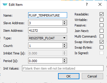
1 - Monarco with Rexygen and modbus driver
2- Coriolis flow controller with ModBus protocol
3- Analog data logger also controlled by Modbus protocol with a pressure transducer read by it
4- Servo actuated valve.
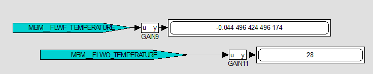
All the Modbus commands and data works fine. The signals from the flow controller, pressure transducer are linked to a TRND block. The ARC block is set.
The problem is that the data is not always correctly stored - even after correcting RTC issues, some experiments end at the wrong time stamps at the CSV file... Other times entirely groups of experiments just vanishes. I can not access the data from any other day besides the current one....
Please..... how is the correct way to properly set the ARC and TRND blocks to register the signals with good time resolution?
") It works good enough.
It works good enough.